-
What is the working principle of an external gear pump?
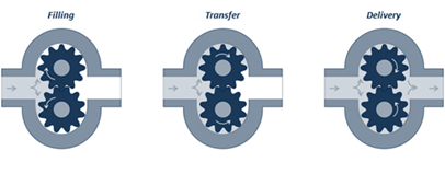
There are 3 stages in the operation of an external gear pump: filling, transfer, and delivery.
Filling:
In gear pumps, the product is pushed to the gears by the pressure on the suction side. The gears rotate in such a way that they open on the suction side.
Transfer:
When the teeth open, the space between these teeth is filled with product. The product then rotates to the discharge side.
Delivery:
On the discharge side, the product is pushed out by the interlocking teeth, towards the discharge line.
Constant and pulsation-free flow:
Thanks to this principle, there is an almost constant flow of the product from the suction side to the discharge side. As a result, the gear pumps can pump the product pulsation-free.
-
An external gear pump is configured specifically for the process for which the pump is selected. This benefits the reliability and accuracy!
These are the components of an external gear pump:
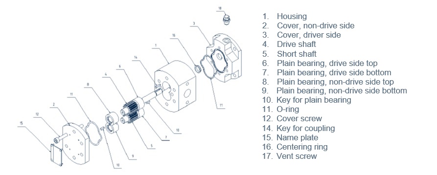
The following should be noted:
- The pump housing of a gear pump can be two-piece or three-piece.
- The O-rings between the housing and the lid and/or mounting plate are not always necessary.
- The bearings are plain bearings and are lubricated by the product during pumping.
-
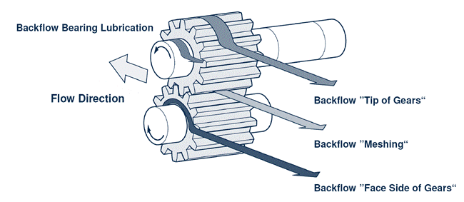
Although the clearances are exceptionally minimal (range of μm) for the gear pumps that Suurmond supplies, the clearances are needed to make the pump work. Through these clearances, however, product flows back from discharge to suction side.
There is also a desired leakage of the product through the bearings to the suction side of the pump. Desired because this leakage creates a lubrication film between the shafts and the bearings.The amount of leakage depends on the following operating conditions:
- Viscosity : the lower, the more leakage.
- Differential pressure : the higher, the more leakage.
- Speed : the lower, the more leakage.
- Temperature : depending on the temperature, clearances can be larger or smaller.
-
A magnetically coupled gear pump is a pump that is hermetically sealed off from the atmosphere.
From a classic perspective, a pump, including a gear pump, is equipped with at least one seal. This seal on the external drive shaft prevents the pump from leaking. Depending on the application, this seal is executed as an oil seal, socket gasket or sliding ring seal (single or double).
In the case of a magnetically coupled pump, a magnet is placed on the drive shaft. This magnet is encased with a magnetic sleeve, which is mounted on the pump.
The statically sealed (often with an O-ring) magnetic sleeve ensures that the inside of the pump – where the product is in the pump – is hermetically sealed from the outside air, the atmosphere.
To power the pump, a drive is attached to the pump (alignment-free) by means of a lantern piece or pedestal. A magnet is also placed on the output shaft of the drive. When the drive is running, the outer magnet takes the inner magnet with it and the pump is driven.
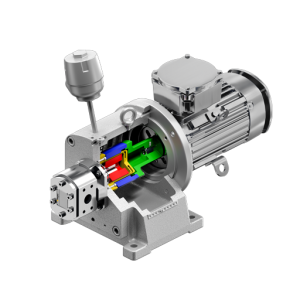
Magnetic coupling for MAAG gear pumps
FAQ Cavitation
-
Cavitation is caused by poor filling of the pump. When the flow to the pump is insufficient, the “NPSH available” (Net Positive Suction Head) will be lower than the “NPSH required”.
The fluid flow will be insufficient to fill the pump and vapor bubbles on the suction side will flow into the pump. These vapor bubbles are compressed and will implode on the discharge side. These implosions cause damage to the pump parts. This will eventually damage the pump in such a way that it loses its function.
The cavitation reveals itself as a metallic noise from the pump. Cavitation will cause damage to the pump.
-
There are several possible causes for a pump to cavitate:
- The engine speed is too high
- The suction pipe is too long
- The resistance in the suction pipe is too high
- The vapour pressure is too high, or the suction pressure is lower than the vapour pressure of the liquid
- The pressure in the flow vessel is too low
-
Due to the above causes, the liquid flow will be insufficient to fill the pump and vapor bubbles on the suction side will flow into the pump. These vapor bubbles are compressed and will implode on the discharge side.
These implosions cause damage to the pump parts. This will eventually damage the pump in such a way that it loses its function.
-
The pump must be inspected, and damaged parts replaced. The cause of the cavitation must be determined, and necessary actions must be taken to avoid further cavitation.
-
To avoid cavitation of the pump, always check if the NPSHavailable > NPSHrequired and take the necessary steps to create the optimal circumstances in your installation (see above).
Check the FAQ about NPSH to find out more about NPSH!
Our Suurmond specialists will be happy to support you to find a solution for your problems with cavitation or to prevent problems due to cavitation!
FAQ NPSH
-
NPSH means “Nett Positive Suction Head”; the nett pressure that remains (after deducting all the pressure losses) at the entrance of the suction side of the pump.
As the gear pumps Suurmond supplies are also used with high vacuum at suction side (especially underneath reactors and with distillation), it is very important to know the NPSH value.
-
NPSHR is the minimum pressure required. This is the value the supplier of the pump should confirm. For gear pumps, this value depends on the viscosity and velocity of the pumped fluid, as well as the pump speed and the design of the inlet channel of the pump.
Basically, you can say that the pressure drop between the inlet of the pump and the point where the fluid is entering the teeth of the gear pump, is equal to the NPSHrequired. To get the fluid in the rotating gears, we need some extra force (pressure).
The NPSH is influenced by different factors, like:
- The higher the viscosity, the higher the NPSHrequired
- The higher the pump speed, the higher the flow, the higher the NPSHrequired
- The bigger the opening, the lower the velocity of the fluid in the channel, the lower the NPSHrequired
-
NPSHA is the available NPSH in the system.
This is the value the pump user must calculate and it depends on the installation. It is the absolute pressure at the suction side of the pump available.
-
Classically it can be calculated with the formula:
NPSHavailable = Ptank + h – dPpiping – Pvapour.Ptank:
The pressure in the tank/vessel/container in front of the pump
h:
The height of the liquid in the tank above the centerline of the pump
dPpiping :
The pressure drop in the piping between the tank and the opening of the pump
Pvapor :
The vapor pressure @ operating temperature of the liquid
Pvapor is an often-forgotten value when calculating the NPSHavailable, but the most important one.
When the absolute pressure at pump inlet is below the vapor pressure of the liquid, gas will occur and the gear pump will not function (cavitation, no lubrication, etc.)
-
If the NPSHA is lower than the NPSHR, the pump will cavitate! Cavitation may cause damage to the pump and stop the process the pump is used for.
To avoid cavitation in the pump:
NPSHavailable > NPSHrequired
For more information about cavitation, check the FAQ!

Our specialists are here to advise on the optimal solution for your process. Our engineers will design a system for you according your specifications.